

YahooGroup
-
Posts
14 -
Joined
-
Last visited
Content Type
Profiles
Forums
Gallery
Events
Posts posted by YahooGroup
-
-
This is a transfered topic from the ASA Yahoo Group.
Posted By: peter2a6 Sun Mar 31, 2013 8:21 pm
I am suffering from what appears to one or more loose elements in my 2" ASA
corrector. Some in this group have had success correcting this problem by
tightening the retaining ring on the element closest to the secondary mirror.
Does anyone know if the lens cell has more than one of these retaining rings? In
other words, will tightening the exposed ring (end near secondary) apply
pressure to the remaining elements in the lens cell? I would expect this not to
be the case.
Peter
____________________________________________________________
Posted By: aperezam Mon Apr 1, 2013 4:53 pm
Hi Peter,
The one at the end of the corrector is the only retaining ring.
Taking it out you can dismantle the whole thing, and yes, tightening
it will apply pressure to all the elements in the lens cell.
Best regards,
Antonio.
____________________________________________________________
Posted By: peter2a6 Tue Apr 2, 2013 2:55 pm
Thanks Antonio!
Peter -
This is a transfered topic from the ASA Yahoo Group.
Posted By: hadrian1805 Tue Apr 2, 2013 5:03 pm
I should know better but I replaced my old XP 32bit machine with a Win 7 64bit
pc to run the telescope and upgraded to ACP 7. AutoSlew 5.1.1.2 won't connect
with ACP 7. With a new install of ASCOM 6 sp1 trying to start AutoSlew from ACP
or trying to Connect ACP to a running AutoSlew I get a Microsoft.VisualBasic
window pop up with the message 'Conversion from String "" to type 'Integer' is
not valid'. The ACP window has the correct values from AutoSlew displayed at
this point but if I click on the 'ok' button to close the VisualBasic window,
ACP disconnects.
I seem to remember this happening in some early versions of AutoSlew and there
was much finger-pointing about which software was at fault. Can a solution be
found or can someone recommend something other than going backwards?
Bill Martin
__________________________________________________________________
Posted By: bernd_eppinger Wed Apr 3, 2013 1:35 am
Hi, Bill,
I remember that somebody had a similar problem shortly after I had bought my DDM60 (quite some time ago), but I can't find the post anymore.
As far as I remember, the problem was that Autoslew seems to use locale dependent numeric formats in the INI-file. Most importantly, the different interpretations of "." and "," between e.g. German and English WINDOWS seemed to be a problem.
If the bug hasn't been fixed in the mean time, and if you use your configurations or ini-files from your previous XP-machine, it might help to set the numeric format to the same values it had under XP. If you can't remember it anymore, you might try to swap the decimal separator between "." and "," and make sure that the character you use for it is not used anywhere else.
Best regards,
Bernd
__________________________________________________________________
Posted By: hadrian1805 Wed Apr 3, 2013 10:29 am
Hi Bernd,
Good tip. It has to be something like this so I will check the .ini files from
Autoslew and dig out the old file from the XP machine in the corner. ACP 7
seems to accept the info from Autoslew and displays it correctly at first but
when I close the popup window it disconnects. ACP 6 didn't do this with
Autoslew 5.1.1.2 in XP so I have too many variables at the moment.
Kind regards
Bill
__________________________________________________________________
Posted By: dale.liebenberg Wed Apr 3, 2013 10:36 am
Hi Bill,
I use ACP 7 on Win 7, 64 bit without problems connecting to AS.
I had this problem many moons ago and it had to do with missing data from my observatory ascom connection, which connects at the same time as AS.
Check under ACP preferences and/or open your other hardware connection setups and maybe you can find the problem.
Dale
__________________________________________________________________
Posted By: hadrian1805 Wed Apr 3, 2013 12:04 pm
Ah. Quite right. I forgot that the dome connects with the telescope if it is
enabled. I will disable them separately and see what happens. Thanks Dale.
Bill
__________________________________________________________________
Posted By: dale.liebenberg Wed Apr 3, 2013 1:31 pm
What dome controller are you using? It is not PierTech by any chance?
Dale
__________________________________________________________________
Posted By: hadrian1805 Wed Apr 3, 2013 8:11 pm
Hi Dale,
Yes, it's Pier Tech and this was the problem. I reinstalled the original ASCOM
driver and it does not give the VB error now. Sadly it has a problem with the
new pier so I have to disable this at the moment. Been here before and I need
to get Darren to do a fix (again). I have a new Foster Systems controller that
I was going to use but this also has a (different) pier problem. Stan Ralph has
not responded to this yet. Forces of Darkness...
Bill
-
This is a transfered topic from the ASA Yahoo Group.
Posted By: nomis_ch Thu Mar 28, 2013 2:17 pm
Hello !
I am a computer-science engineer working gro the University of Bern.
We recently bought an ASA DDM160.
We are using autoslew 5.1.1.5, with the addition of the small accelerometer to
facilitate Zenith parking.
The FindHome method of the ASCOM driver is not implemented, is that done on
purpose or is it gonna be implemented ?
This method would be very useful as we are developing an automated observatory
and I would like the scope to make a findhome on when Autoslew starts (either
from ascom calls or through an Autoslew option).
Furthermore, when I do a findHome from Autoslew (clicking on the button), the
mount succesfully find the home but it also modifies the Parking position 1 to
the position found by FindHome. Thus the scope is not anymore looking at the
zenith in P1 ....
Furthermore, it seems the "Set new Homeposition" function is not working. I
wanted to use it to put the new home position (reference marks ?) closer from
the Zenith position but it does not have any effect when I press on it. (It
shows a message asking if I am sure I have synched and centered the scope ... I
press yes and nothing happens)
MY colleague, M.Affolter also contacted you concerning safety concerns. If the
USB gets disconnected while a command was issued, the scope will continue moving
in that direction .... it should have a king of hardware stop ... or something
similar ...
Best regards,
Simon Ruffieux
________________________________________________________
Posted By: lukasdemetz Thu Mar 28, 2013 4:43 pm
Hi Simon,
I am not sure, but there are a few ASCOM-specifig configuration options in Autoslew under Control -> Ascom ACL. Things like “Enable ASCOM to Homefind” and “Homefind on unpark” might do de trick for you. I use these as I need Autoslew to do a homefind as soon as it starts (used with ACP).
For the USB issue, try different cables; I had just a few days ago a similar issue with an active USB cable (funny enough, the “normal” cable is not causing these errors).
Hope it helps
Lukas
________________________________________________________
Posted By: georgecarey47 Thu Mar 28, 2013 5:16 pm
Hello Simon,
It will be interesting to hear how you get on with a DDM160!
One bit of advice, ASA do not always read this forum regularly, so it might be
better to put in an official support request to ASA to get your questions
answered.
George
________________________________________________________
Posted By: bernd_eppinger Fri Mar 29, 2013 12:33 pm
Hello, Simon,
concerning the homefind issues:
> "The FindHome method of the ASCOM driver is not implemented"
I know that it is implemented and that it works, because I have a working self-written MATLAB-script which uses this method. However, to make it work, it is necessary to change an option in Autoslew:
Control -> Ascom ACL -> Enable Ascom to Homefind.
> "when I do a findHome from Autoslew (clicking on the button), the mount [...] modifies the Parking position 1 to the position found by FindHome."
When you start the mount without homefind and without synching and from an unknown position, and then do a homefind, then the homefind will change all positions in the sky, not only the park positions. For example, if you do a slew to an object before the homefind, and if you repeat the same slew after the homefind, the telescope will point somewhere else. This is an expected behaviour. For details, I'd recommend to read the Autoslew manual, but I here are some basics, as far as I understand the Autoslew documentation.
My DDM60 (and I expect also the larger mounts) has no absolute angular encoders, but instead differential encoders. This means when you power the mount up, then it does not know where it is pointing to. Autoslew tries to alleviate this by storing the last position, but of course this can only work if the mount is not moved while powered down. So for the general case, the mount must first find out the absolute angles of its encoders. This is done by homefind.
Homefind tries to find the "Reference marks" of the encoders. These are mechanically fixed marks in the encoders, of which the absolute position is known (or at least constant). This is called the Homeposition, and its value is stored somewhere in the INI-files. When the mount finds the reference marks, it knows the absolute position of its encoders, and it replaces the encoder readings with the known Homeposition. From now on, the encoder readings are "correct", as far as the stored Homeposition is correct.
If you do a slew to a park position before a homefind, then the slew (like any slew) will be to anywhere. Of course you can manually slew to any position and also set park positions, and the mount will also be able to slew to these park positions again. But these positions are relative to the encoders which have an unknown offset at this time. When you do a homefind, the offsets are corrected. If you repeat the same slew now, the telescope will point somewhere else.
When you have a new mount and want to maximise the precision you can achieve without a configuration / Pointing model, I would recommend to do the following once:- Telescope base should be and stay horizontal (or something equivalent with the DDM160) to make the whole thing reproducible.
- Homefind.
- Polar align the mount as precisely as possible (may need multiple iterations).
- Clear the Configuration.
- Homefind again (just to be sure; I don't know if this step is necessary).
- Sync to a star (-> now Autoslew knows where it is pointing in the sky).
- Set new Homeposition.
Now the stored Homeposition is "calibrated", i.e. has the correct DE and hour angle coordinates, assuming that there are no telescope errors. You should never again do a "set new Homeposition", as this would change your calibration. From now on, each time you power up the mount, the first thing you should do after magnetic angle autofind is a homefind. Only after this homefind, the positions to which the mount points are defined and reproducible. This includes the park positions.
Addendum 1: Instead of homefind, it is in principle possible to do a sync to a star, but I find homefind easier.
Addendum 2: Apart from homefind, changing the clock of your computer also influences where the mount is pointing to. Therefore, I use a GPS. As Autoslew syncs the computer time after each slew and my initial computer time may not be precise, I do a dummy slew to set the correct time, and then I do the actual slew. If apart from the time, my date is also wrong, then I have to update the date by hand; unfortunately, Autoslew doesn't do it.
> "it seems the "Set new Homeposition" function is not working. I wanted to use it to put the new home position (reference marks ?) closer from the Zenith position but it does not have any effect when I press on it. (It shows a message asking if I am sure I have synched and centered the scope ... I press yes and nothing happens)"
I think this is a misunderstanding of what "set new Homeposition" is supposed to do. It doesn't and cannot change the position to which the telescope is moving during a homefind, because the telescope must move to the reference marks which are mechanically fixed and cannot be moved to a different position by software. If you want to move your telescope to predefined positions, then use the park positions instead (of course after doing a homefind).
How to use "set new Homeposition": It requires, that you have made a homefind. This tells Autoslew where further positions in the sky are relative to the reference marks. After that, it requires that you synced your polar aligned horizontal mount/telescope to a known position in the sky, usually a star. This allows Autoslew to determine an offset between the reference marks and the DE / hour angle. Now when you select "set new Homeposition", then this offset is simply saved to disk. You will not notice any effect during the same Autoslew session. But if you stop Autoslew, power down the mount, then power everything up again and do a homefind, then you should realize that Autoslew will now be able to slew directly to your star, without synching.
Addendum: Homefind and "set new Homeposition" are the first step to a precise mount orientation. It does not correct for telescope errors, mount angle etc. For these things, you must make a Pointing model (sometimes also called Configuration). I have the impression that if you use a pointing model, then the "set new Homeposition" is probably redundant, but for me as a mobile user it is nevertheless useful because it helps me to do a first coarse alignment after homefind when I do not yet have a valid pointing model. When you have and use a pointing model in a stationary set-up, then the only important thing is that from now on you don't change the homeposition ("set new Homeposition"), as this would make your pointing model invalid.
Best regards,
Bernd
________________________________________________________
Posted By: tomtom2509 Tue Apr 2, 2013 11:21 am
Hi Bernd,
you wrote:" When you have and use a pointing model in a stationary set-up, then
the only important thing is that from now on you don't change the homeposition
("set new Homeposition"), as this would make your pointing model invalid."
I don't think that it invalid a pointing file because the only thing you change
ist the delta to the reference marks. I the german AS-manual I found this:
"Nachdem Sie ein Pointingfile (welches Sie in Zukunft verwenden wollen) angelegt
haben, können Sie nun eine
neue Homeposition setzen. Dies dient dazu, dass Autoslew die
Positioniergenauigkeit der Montierung im Hinblick auf die erstellte
Pointingdatei übernimmt."
Which said that it is recommended to set a new homefind positon after making a
new pointingfile.
Or do I have a missunderstanding in this case?
BR Thomas
________________________________________________________
Posted By: bernd_eppinger Wed Apr 3, 2013 1:05 am
Hi, Thomas,
I think your understanding of the German version of the Autoslew Manual is exactly as it is written, although the important part is in parentheses. However this is one of the parts of which I think that they could be clearer in the manual.
When I look into the Advanced Pointing Control window, I can see that each configuration has its own "Synch Offset". Different configurations have different Synch Offsets, which is obvious for my mobile set-up. Under "Pointing -> Show Corrections", I can find them as "Offset Constant". This shows clearly that each configuration stores its own Synch Offset.
It seems also obvious that this Synch Offset must be adapted, if the angles which Autoslew assumes for the reference marks change. The only alternative I can think of would be that Homefind does not correct the encoder reading, but instead modifies the Synch Offset. However I have checked that this is not the case.
Following these findings, there's some room for interpretation of the manual text, especially the sentences that follow. I personally don't think that Autoslew changes the Synch Offsets of all configurations I have stored somewhere on disk when I do a "Set new Homeposition". The manual says that I should load the configuration that I want to use in future, then save it as "Use now, save and use on next start", and then do a "Set new Homeposition".
Interpretation 1: Autoslew does not correct any configuration on disk. In this case, I will in future need to synch after the homefind (unless I make a new pointing file), which would not be the purpose of homefind.
Interpretation 2: Autoslew modifies the Synch Offset of the currently loaded configuration, or of the configuration that is automatically loaded on start, when a "Set new Homeposition" is done. This would then make all other saved configurations invalid, and the modification of the configuration would be somewhat unexpected.
It would in principle be possible to try and find out what Autoslew actually does during "Set new Homeposition", but I don't want to lose my saved homeposition.
Anyway, I think it is safest to do "Set new Homeposition" only once, then make a new configuration, and then never again change the homeposition. This should hopefully avoid the effects of these unclear parts of the manual.
Best regards,
Bernd
________________________________________________________
Posted By: nomis_ch Fri Apr 5, 2013 10:27 am
Hello everyone,
First of all, thanks to all for your replies.
Concerning the FindHome function from Autoslew, I indeed found the "hidden" option; thanks for pointing that out.
The "HomeFind" and "set new homeposition" procedures are much more clear now. Still not as clear as I would like to, but your explanations helped me a lot (Specially bernd's detailed explanations). I am still working on that part to be sure it will perfectly work with complete remote automation.
Concerning the USB-cable disconnection problem, it is not a problem of the cable. I disconnected it myself to see the behavior. The problem is ASA not having taken into account the fact that a USB cable may be disconnected or that the program/computer where Autoslew is installed may fail (blue-screen, power off, ...). So in the case of a failure, it should (hardware wise) detect it and stop the motors instead of continuing forever in the last directions received. Because the actual behaviour could break the scope (hitting the pier). Indeed all limits and controls are software, there should be mechanical/hardware stops on the mount.... or something similar. We already informed ASA and they told us they were working on it. We thought about adding sensors ourselves and shut down power in case of emergency, but with the inertia, the scope may still hit the pier.
Otherwise, we are quite satisfied with the mount itself. (Just a bit disappointed with manuals and software not being too clear, notably translations being sometimes a bit approximative). I also would like some automatic way to detect east/west orientation using the small accelerometer ... that would not be too complicated to develop, I guess.
________________________________________________________
Posted By: dwein6889 Mon Apr 8, 2013 4:29 pm
Dear Simon,
About the accelerometer, did you get this part from ASA? So what will you
develop in that case?
Best regards,
Dietmar Weinzinger
ASA
________________________________________________________
Posted By: w.boot49 Mon Apr 8, 2013 6:35 pm
Hallo Dietmar,
I would think that is a secundary function of the encoders...
Or am I totally wrong here?
Best Regards,
Waldemar
________________________________________________________Posted By: dwein6889 Tue Apr 9, 2013 8:56 am
Hello Waldemar,
This is a new unit(USB plug), we are in the Beta test level now.
Best regards,
Dietmar Weinzinger
ASA
________________________________________________________
Posted By: nomis_ch Wed Apr 17, 2013 9:36 am
Hallo Dietmar,
I will not develop anything using the accelerometer (ASA sensor) that was
provided from ASA.
What I meant, is that, using this accelerometer, you should be able to
automatically detect the current pier side (east or west) of the mount.
Currently we have these two options "Ask" or "Decide". Therefore you should
provide an option "Decide using ASA Sensor" which would make much sense when
remote operating the mount.
Simon -
This is a transfered topic from the ASA Yahoo Group.
Posted By: astrowhwiii Wed Apr 17, 2013 5:37 am
hiya
i have a good pointing model, but have had to move my DDM60.
i recall reading about a way to easily reposition the mount without building a
new pointing model. does anyone have a link to the technique?
thanks
-bill w
_____________________________________________________
Posted By: bernd_eppinger Wed Apr 17, 2013 9:15 am
Hi, bill,
Maybe you mean the Super Fast Polar Alignment method by Philipp Keller. See here:
http://forum.astrosysteme.com/index.php?/topic/42-very-simple-and-fast-polar-align-method/
The method uses a previously made pointing model to get the polar alignment when the mount is repositioned. This is done by centering a star with the polar alignment screws. It is then assumed that if the polar alignment is the same, then the pointing model can be reused.
However, in my opinion, the method in this simple form has a theoretical flaw and can therefore only be considered as an approximation: The orientation of the mount has 3 degrees of freedom. The alignment to a star resolves only 2 of them. One degree of freedom therefore remains. For example, a star can be centered with the same RA- and DEC-motor position with either a horizontal or a slanted base-plate. Unless this extra degree of freedom is controlled by other means, the polar alignment will therefore not be reproduced by the method.
Note: I try to control the extra degree of freedom by using a self-made Alt-Az-style polar alignment and controlling the orientation of the mount plate with a precision spirit level. But the reproducibility is still poor, probably because I can only poorly reproduce the orientation of the telescope on the mount's dovetail plate. Replacing this by a more reproducible mechanics will be one of the next things I have to do.
The following may work for you, but only if your old mount position had a good polar alignment: The first step is to try to get a very good polar alignment at the new location, too. The SuperFastPA method may give you a start value, but you will need additional iterations. Once you achieved good polar alignment, you still have the rotation of the mount around the RA-axis as an unresolved degree of freedom. This can (hopefully) be resolved by loading your previous "good" pointing model, then syncing to a star, and then saving the resulting pointing model under a new name and using it in future.
As a better alternative to the last step, you may use the "3 star Polar Alignment with same Declination, optimizing Polar Alignment only" option. See:
Autoslew5100.pdf
Best regards,
Bernd
_____________________________________________________
Posted By: portaball2001 Wed Apr 17, 2013 10:56 am
Hi Bill,
As Bernd already pointed out it is possible to realign a repositioned
mount quite easily within a few minutes. I have to do it every time when
I setup my mount ( I have no permanent pier).
I do following steps:
- Setup mount and try to polar align as good as possible ( a built in
laser is a big help)
- Start Autoslew with your old pointing file and Home position the mount
- Slew to a brighter star close to the meridian in the south (alltitude
20deg - 40deg)
- Center the star in the field of view with the adjustment screws of the
mount
- Generate a three star autopointing file with Sequence ( there is a
special option there to do this)
- Load this autopointing file in Autoslew and do a 'Calculate
configuration' with the 'Three star' option ( the first one in the
pop-up window), which will just update the currently pointing file in
use
- Save the updated pointing file with the 'Use now' or 'Use now and load
next time' option.
This procedure usually brings me within five arc-minutes of the pole,
which is good enough for ten minutes exposures ( and probably more) with
my equipment (f=900mm).
Best regards,
Gerhard
-
This is a transfered topic from the ASA Yahoo Group.
Posted By: philipp_keller Fri Oct 21, 2011 9:05 am
maybe somebody wants to be first to try this method I thought about ?
SuperfastPA.pdf
Super fast Polar Alignment with DDM mounts
This manual describes how to use the homefind and 1 star to quickly polar align
the DDM mount which will be very interesting for mobile observatories.
How it is done now
1. Use the Laser to roughly setup the mount
2. Make a 4 star pointing file on one pier side, let Autoslew move the star
according to the calculated error and re-center it with Azimuth and Altitude
screws
3. Make one more pointing file containing both sides and use that for the
following sessionNew Super Fast PA
1. Setup the mount roughly north aligned (+-4 degree)
2. If you are at another location compared to your last setup then set the right
mount location in Autoslew (Mount/Location).
3. Make a home find
4. Slew to a star in the south between 20 and 50 degree above horizon
5. Center the star not with the gamepad or motors but only with the Azimuth and
Altitude screws or of this is not enough by moving the tripod/pier.
6. Use the old pointing file from last time, it will do for most purposes. It
will definitely be good enough to work with the new MLPT method.
Requirements and understanding the new method
Homefind gives a very good repeatability usually better than 0.5 arc minutes.
When the only thing that changed is the position and angle of the mount (if you
have a mobile setup) then you should of course be able to get into the same
status as last time by simply making this homefind (Ra and Dec is OK now) and
then pointing the mount to the selected star by using Azimuth and Altitude
alignment. Its sounds incredibly easy.
Of course to successfully apply this method you must have set your homeposition
during your last session and you need a decent MASTER pointingfile. So here is
how to end the last session if you want to start your next sessions with the
Super Fast PA:
1. Be polar aligned as good as you can because you will COPY this polar
alignment error from now on to the next sessions. So try to be below 5 arc mins.
2. Make a homefind (if not done anyway on start)
3. Make a nice pointing file, calculate Configuration and select Use and Save
for next start.
4. Point to a star near south (roughly the same place AND PIER SIDE you will
take next day for your Super Fast PA), center it and synch
5. Set new home position (Mount / Set new Homepositon). The steps 4 and 5 ensure
that your offset (error) is minimized at the place where you will select a star
for PA the next dayOf course the accuracy of this method depends on how the repeatability of fixing
the telescope on the mount is. So try to keep this the same every time. -
Posted By: sinkepinke Thu Apr 4, 2013 3:56 pm
Hi,
I'm considering buying this mount in the near future so I'd appriciate your
feedback.
Max weight for DDM60 is 28kg, but I'm wondering if the /2 rule for max weight
for AP use still applies to a mount in this price range? Or I can go higher than
14kg and still benefit the high performances of this mount?
Regards,
Sinisa Steblaj
_____________________________________
Posted By: schmidmahler Fri Apr 5, 2013 1:04 am
Hi Sinisa
As long as you have good balance the DDM60 will be precise. I run the mount with
approx. 15 kg without any problems. I think it would carry much more if needed.
Precise balancing takes some time with this mount but thanks to the new autoslew
software version it is now really easy to find the right PID-parameters to run
the mount. This is a great piece of hardware! I have mine since about 6 months.
I don't want another mount anymore, but would like to get rid of all the other
small imperfections that come into play with this high precision like fixation
screw tension of my roll-out pier setup and such things.
The mount will do a great job once you have good balance and the right
PID-parameters as well as a good pointing model. The only time it became
unreliable was with imperfect balance and wrong PID-parameters but this was with
an old version of autoslew.
Dani
_____________________________________
Posted By: dale.liebenberg Wed Apr 10, 2013 10:40 am
Hi,
I am using a C14 on my DDM 60 with a total weight of about 25kg.
With this kind of weight I found:
Balance is critical
It does battle to keep steady in windy conditions.
But, I have managed to get it working successfully, particularly after installing a dome to reduce the wind effect.
Dale
_____________________________________
Posted By: pauloastro69 Thu Apr 11, 2013 6:40 am
Hello Sinisa,
I'm using an Orion AG14 with 26kg(and not the 19kg annoucend in there site) plus
2kg of accessories and 26kg on the counterweight shaft.
And the balance must be very precise for a good PID values calibration.
Best regards,
Paulo Nunes. -
This is a transfered topic from the ASA Yahoo Group.
Posted By: micv2004 Wed Apr 10, 2013 10:11 am
hello,
i have an issue with ok3 focuser (old one, bought in 2008), with ascom 6, and
focusmax 3.7.0.36: i can not connect the focuser to focusmax.
i found the ok3driver in the choose list of ascom/focusmax, but i have an error
message with "cant find progID" , something like that.
i have try another driver from asa website (the one after may2010), but it don't
work standalone, impossible to connect,he don't find the focuser on com 5.
the old asa driver v2.0 (first one), work in standalone.
the computer is a new one with xp pro 32.
anyone can help me to find a solution?
may be i can try with old version of focusmax?
thank you in advance , my hairs start to fall on floor...
michael
________________________________________
Posted By: micv2004 Sat Apr 13, 2013 10:41 am
anyone to help me?
thank you
________________________________________
Posted By: micv2004 Sat Apr 13, 2013 3:39 pm
anyone?
regards
________________________________________
Posted By: tekic545 Wed Apr 17, 2013 2:29 am
I also have a 2008 model of the OK3 focuser. I use a Bakhtinov Mask for
focusing, but would very much like to use FocusMax.
If you've succeeded in making your OK3 work with FocusMax, we'd like to hear
from you.
Thanks,
Bob Gillette
________________________________________
Posted By: john_carver0 Wed Apr 17, 2013 4:55 pm
Bob,
I have a ASA 16inch with the OK3 heavy duty focuser. I have been using it with
FocusMax and ACP successfully for 3 years. I am using a Apogee 29050 camera
right now. I use to have a Apogee U16M camera before.
So again yes I have successfully -and at present- used Focusmax with OK3 focuser
and heavy duty focuser. However over the past 3 years I have had to reinstall it
because of new computer, software failure,ect. Each time I have had to reinstall
OK3 focuser drivers it has been a real headache on the OK3 software side not
FocusMax. Thus I always clone all of the hard drive using Acronis to avoid
having to reinstall any of the OK3 drivers. It always takes at least 1 to 2
hours of failures and then out of the blue success to reinstall OK2 drivers
cold. FocusMax is easy. Sometimes it seems like Black magic. If you would like
to talk with me I can be reached at my veterinary practice phone # 972-578-2553,
Skype as - astroveterinarian, or email res0hver@.... It can be done with
great success and it is well worth it. But it requires work and dare I say
witchcraf -
This is a transfered topic from the ASA Yahoo Group.
Posted By: doug_landmann Thu Apr 18, 2013 5:27 pm
Why is it that get two different answers for the thickness of the adapter
required if I use the ASA calculator or and if I take the optical backfocus
number from SBIG and subtract it from the ASA backfocus requirement?
ASA 10"N Wynn 3" corrector f/3.8 backfocus from Chart A = 57.29mm
Which is the same number that comes up in the spreadsheet calculator for the 10N
with Wynn 3"corrector at f/3.8
Using the calculator and accepting the 1mm glass thickness over the CCD sensor
and 3mm filter thickness and inputting 44.74mm for the backfocus for the SBIG
STXL-11002M with standard filter wheel. The calculator returns the adapter
thickness of 13.87mm.
Using SBIGs Optical backfocus number (42.77mm) and simply subtracting that from
the 57.29mm total backfocus the result is 14.52mm. a difference of 0.65mm. Is
that number significant? Should I not worry about it Would you error in favor
of the ASA calculator or the SBIG optical focus number?
Thanks in advance for your input.
Doug Landmann
_____________________________________________________
Posted By: portaball2001 Fri Apr 19, 2013 1:14 pm
Hi Doug,
The formula for the path increasement of light in a media is (r - 1)/r, r being
the refraction index.
For glass r = 1.5, which gives a delta of 0.33*thickness_of_media.
In your example(thickness_of_media = 4mm) delta is 1.32mm.
Necessary adapter length: 57.29mm - 44.74mm + 1.32mm = 13.87mm
The ASA calculator is right, SBIG's specified optical length is wrong.
Best regards,
Gerhard -
This is a transfered topic from the ASA Yahoo Group.
Posted By: konihlav Sun Apr 21, 2013 12:51 pm
Hi group,
I am a bit frustrated with my new ASA Newtonian. The PDF manual is grossly
inadequate and poor on information
(http://www.astrosysteme.at/images/Collimating_ASA-Astrographen_E.pdf). I try to
calm down my emotions now though it's not easy as I wonder if the guy who
invented the mirror holding system (3 allen key screws) was a real genius or an
real ..... :-(
OK, gang, please could some of you shed more information and give tips on how to
operate these so called pull and push and traction and pressure screws (there
are 4 different names for 2 different screws used in the manual which is really
confusing and annoying)? What sequence to use, how many turns to make and any
other practical tips on how to mechanically adjust the primary mirror. What to
do and what never do in order to make the collimation last (I do not have any
fixed place or an observatory so this nightmare will be present every time I
want to use the ASA astrograph for imaging).
The biggest stupidity in the manual is on page #5 above Image 11, I am citing
the original "In order to collimate the main mirror, start by first turning one
of the pressure screws (max. 5 mm) then fasten with the help of the traction
screw while turning the second pressure srew until end stop (see Image 11)."
COULD PLEASE SOMEONE EXPLAIN the meaning of
- the max. 5 mm ??? is it just an information on total travel the screw can
make? or anything else?
- fasten with traction while turning... ? how can I fasten one screw while turn
the other??? should I operate two allen keys at the same time? or in which
sequence should that be done?
- what "until end stop" really means?
if I fasten the middle screw and then the other side screw the remaining side
screw remains loose.
I tried to play with my mirror a bit and it doesn't move at all. I had to loosen
all three screws to make any movement apparent - using a laser collimator (and I
really have the mirror in almost vertical position). BTW my tools are Blackcat,
Infinity and Howie Glatter.
thanks for any tips and howtos. I am not so big idiot as I seem even though I am
Newtonian newbie, because I know how to collimate ordinary simple SkyWatcher
Newtonian, I know how it works, the only thing that I do not understand is HOW
TO MECHANICALLY ADJUST ASA'S SYSTEM holding primary mirror. It seems too
complicated to have 3 screws.
thank you!
best regards
Pavel
_______________________________________________________________
Posted By: bernd_eppinger Sun Apr 21, 2013 6:20 pm
Hi, Pavel,
I don't have an ASA astrograph, but I speak German, and I think the German version of the manual is easier to understand.
Here is how I would understand and translate the text of figures 10 and 11:
Fig. 10:
After that, adjust the primary mirror using the pull- and push-screws. First loosen the Pull-screw by turning it counter-clockwise.
Fig. 11:
For adjusting, turn one of the 2 push-screws (max. 5mm ?!?), then lock it with the pull-screw, and then turn the other push-screw in the same direction until it reaches a stop.
I can't tell you what the "5mm" means, but I have the impression that I understand the rest, although it could be written clearer. The following is my understanding. I think that for locking the mirror holder screws, they use two push-screws that work against one pull-screw for each of the 3 adjustment positions. That avoids inserting too much strain into the mirror holder.
As the telescope is pointing up during adjustment, the weight of the mirror is initially on the push-screws. Therefore, loosening the pull-screw does not move the mirror holder very much. The next step is to adjust the push-screws. In my opinion, turning only one of them only works when the mirror must be pushed up. The general case will be that both must be turned. After that, the mirror holder will usually lie on only one of the 2 push-screws. After the pull-screw is tightened again, one of the push-screws will still be loose and must be tightened, too. Ideally, both push-screws should have a similar force so that a minimum amount of torque is brought onto the mirror holder.
The German manual also says that the collimation screws should not be tightened too much to avoid strain on the primary mirror.
Perhaps an owner of an ASA astrograph can provide practical collimation tips.
Best regards,
Bernd
_______________________________________________________________
Posted By: konihlav Mon Apr 22, 2013 9:28 am
Hi Bernd,
thank you for your insight, it makes sense to me. Your version makes it clear. I
think I understand it now.
From practical point of view (that's what I am looking for) the 5mm most
probably means the overall length (range) the screws can travel and the primary
mirror can be positioned (changes focus). I was surprised that after loosening
the pull screw (center screw) and one of the push screws (side screw) nothing
happened/changed. Therefore I need to play also with the other side (push) screw
to adjust primary and then, when done, fix the center screw and re-tight (hand)
the other side screw and then it's in fixed position I guess.
Gonna be a night mare to collimate the F/3.8 system, I knew I am walking on a
thick ice when I decided to go this way...
Now I go to order the "tuBlug" from Howie (if he's already back home from NEAF)
because I need to see the laser spot from the back of the telescope. I plan on
using simple Howie laser first and probably won't use the Catseye that I already
purchased - or I would have to figure out a way how to project the tringles with
a webcam on LCD screen to see what's happening from the back end of the OTA...
seems hard job to me now (being beginner is nothing I like)
thanks again
Pavel
_______________________________________________________________
Posted By: bernd_eppinger Tue Apr 23, 2013 12:24 am
Hi, Pavel,
I wish you good success for your telescope collimation.
When I bought a laser, I found it made collimation much easier, because I can now see it from the back of the telescope just as you write it. However, my telescope is an f/5 which is more forgiving.
But if the laser is not precise enough for your f/3.8, you could still use your webcam idea with the CatsEye. By the way, I wonder why nobody had your idea before. It could be quite simple: Something like a CatsEye collimator with a simple lens and a T-Thread for a planetary camera. An advanced version could include a software which inspects the image and tells you which screw to turn in which direction.
Best regards,
Bernd -
This is a transfered topic from the ASA Yahoo Group.
Posted By: dale.liebenberg Thu Apr 18, 2013 1:19 pm
Hi All,
Lately I have had problems when trying to connect to a new instance of AS via
Ascom. The calling app, eg. ACP hangs up.
I traced the problem to 2x Astrooptik processes running.
It seems that the process does not always shut down when AS exits.
When I start up AS again, there are two instances of the process running. Any
idea why this is happening?
Dale
___________________________________
Posted By: bernd_eppinger Sat Apr 20, 2013 10:08 am
Hi, Dale,
Occasionally, I have the same effect. Sometimes, it happens when I do something wrong like disconnecting the USB cable to the mount before trying to shut-down Autoslew, but I also observed it when I saw no obvious reason.
My workaround is to kill the AstroOptikServer.exe with the task-manager when it happens. I don't know how to fix the root cause.
Best regards,
Bernd
___________________________________
Posted By: dale.liebenberg Mon Apr 22, 2013 12:01 pm
That is what I also do. But because it means shutting down AS it can be a problem for remote observatories and manual home find (which I tend to use)
Dale
-
This is a transfered topic from the ASA Yahoo Group.
Posted By: konihlav Thu Apr 25, 2013 3:32 pm
Hi gang,
sorry to disturb with stupid questions, but is there anyone who uses ASA 10"
telescope and 3" 0.95x Wynne reducer/corrector and with 36x24mm CCD camera like
e.g. SBIG STL-11000???
I beg you please, could you show a sample flat field frame (my personal e-mail
address is pablo22 at seznam dot cz)? how much vignetting you get? what filters
do you use? (I use 50mm unmounted Astrodons).
From the PDF papers, ASA claims relative illumination at the edge of 44mm
diagonal to be about 25% at F/3.6 for a 250mm mirror.
My problem is that I don't have STL-11000 but MII G3-11000 from Moravian
Instruments and my first test shot of a flat field looks terrible, like:
http://www.astro.cz/galerie/v/uzivatele/Konihlav/misc/vignetting.jpg.html?g2_ima\
geViewsIndex=1
this is obviously not acceptable for me. I hope the issue is in the front window
being too small see e.g.:
http://www.astro.cz/galerie/v/uzivatele/Konihlav/misc/IMG_4779.JPG.html
thank you all for ANY insight.
best regards
Pavel
______________________________________
Posted By: s2hao3 Thu Apr 25, 2013 4:11 pm
you said the specs were 25% at the edges for a 44mm diagonal for the ASA corrector
your flat is showing about 25% of the peak illumination at the corners: your peak is 44K DN and the corners show a bit more than 12K DN... that’s around 25% so how does changing the sensor to a different brand of camera help you?
it seems to me that the results specified by ASA are basically what you are getting. Or did I miss something?
Also it looks like you might have a guider tap protruding into the illuminated field at the bottom right. Something is blocking some of the light at the bottom so maybe it is the OAG tap?
______________________________________
Posted By: konihlav Thu Apr 25, 2013 4:41 pm
Dear Richard (the sharp "FLI" guy ),
),
thank you for your quick response.
My math is as follows. Based the center of the frame has about 44000 ADU I would
expect to get around 33000 ADU in the corners provided the vignetting is 25%.
But what I get? around 15000 ADU, i.e. vignetting in my case is 66% ! that's
kinda big.
It looks like a similar case to Canon 5D MarkII DSLR (full frame) and fast
optics. With F-stop much faster than F/4 you can see huge vignetting due to the
obstruction in the camera body.
I have already called Moravian to have a look into it. Anyway I STILL WONDER
what a flat field calibration frame looks like from a typical SBIG STL-11000
camera My suspect is that the window in G3-11K is too small (would be the
good case as this would be solvable).
thank you!
Pavel
______________________________________
Posted By: s2hao3 Thu Apr 25, 2013 5:19 pm
I think your problem is with the definition of relative illumination. It doesn’t mean the light intensity drops off 25%, instead it means only 25% survives...
if ASA specfies relative illumination in the corners of 25% that means that the intensity in the corners is 25% of what it is in the middle.
that’s what I see in your plot
what about the protrusion in the lower edge on the right side? Is that an OAG tap?
______________________________________
Posted By: konihlav Thu Apr 25, 2013 6:20 pm
Hi Richard,
I appreciate your opinion and time looking into it. Here:
http://www.astrosysteme.at/images/Corr_3Zoll_Wynne.pdf
you can find the relative illumination for a 250mm scope F/3.8(3.6) it shows a
light fall from 1.0 to 0.75 (i.e. some 25% down). That looks cool to me and
also my result - the center part looks great.
I have already feedback from Moravian Instruments (and some other astro friends
of mine) and I am 99.999% sure it's the central window of the CCD camera on
blame (front window) see this image:
http://www.astro.cz/galerie/v/uzivatele/Konihlav/misc/IMG_4779.JPG.html?g2_image\
ViewsIndex=1
they told me it is only 40x28mm big (small) and it's in 29mm distance of the CCD
chip surface that's is really silly and they admit it because initially
(years back) they made this size as 2" was standard and they did not think of
any 3" accessories :-) seems funny ;D so they will increase the size to 45x31mm
(from 40x28mm) in order to prevent vignetting at F/3.5. They will send me the
front camera cover part as soon as possible
and that protrusion in the lower edge on the right side would most probably be
really the OAG prism so I will move it upwards, should be fine then...
many thanks
sincerely
Pavel
______________________________________
Posted By: s2hao3 Thu Apr 25, 2013 10:47 pm
Yep I agree with the conclusions: the wording of the spec was misleading for me and the result was coincidentally showing a 25% remainder.
The line plot in the first slide really was telling had I thought about it a bit more: there was clearly an abrupt change in slope as the limits of the window functioned as an optical stop.
One point worth making is that if there's any serious light flux drop-off, flat fielding can be adversely affected from a final image SNR perspective. In effect what happens is the final result is flat from a line profile perspective but it will be noisier where the signal level was low prior to calibration.
The line profile can be useful,in illustrating what happens in that scenario. Try flat-fielding a flat image and then look at it using the line profile and it will be apparent.
A good example is shown on pages 27-45 of this:
http://www.narrowbandimaging.com/images/ptc_talk_wsp_2009_crisp_final_comments_web.pdf
In particular see page 33, 34, 38, 39, and 43
If you look closely at the line profile in the upper left of page 33 you will see an inflection point around 10k DN where the vignetting really dominates. That inflection is similiar to the ones in your line profile.
This lens is an f/1.8 so even in the non vignetted regions the cosine^4 light roll off is very pronounced.
Comparing to the larger format f/2.4 lens shown on page 38 and later pages, the delta is striking
Once again it goes to show that using only the sweet spot in the center of these larger lenses offers significant and quantifiable advantages
______________________________________
Posted By: konihlav Fri Apr 26, 2013 10:02 am
Yes, I know your article and I agree.
The image after calibration with flat field would be way tooo noisy. This severe
vignetting is not acceptable.
Good thing is that the solution is on the way. Moravian will produce bigger
front camera cover window and ship it to me ASAP :-) so I hope in 2 weeks I may
have a replacement. It's so obvious. G3-11000 is the biggest camera in G3 series
(there are KAF-6303E and KAF-1001E equipped cameras that are obviously smaller
so the problem is at F/3.6 and G3-11K).
I let you know when I get it and make another flat test.
ANYWAY, IS THERE ANYONE WHO COULD SHOW A FLAT FIELD FRAME DONE WITH SBIG
STL-11000 from this setup to show how it looks like at SBIG ???
thanks!
Pavel
______________________________________
Posted By: o.sedan Fri Apr 26, 2013 10:33 am
Hello Pavel,
Here is a flat taken a couple of days ago, with a STL11k, ASA 10N, 0.95 Wyne Reducer, and L Astrodon 50mm filter :
http://www.astrosandille.fr/images/brutes/flat-023FL.fit
"The image after calibration with flat field would be way tooo noisy. This severe vignetting is not acceptable"
You are right, but I accept it.
Regards,
Olivier
______________________________________
Posted By: daveddm85 Tue Apr 30, 2013 8:12 am
Olivier,
Your flat doesn't look too bad.
I just purchased an FLI PL16803 and Centerline filter wheel. I am waiting on
parts to connect it to my ASA N10 astrograph.
I look forward to seeing how well it performs with this telescope!
Dave
______________________________________
Posted By: adam.jesion Thu Apr 25, 2013 7:28 pm
Hi,
I am absolutely sure that was a sensor window. Here you have my quick photo without any flat frames:
http://astropolis.pl/index.php?app=core&module=attach§ion=attach&attach_rel_module=post&attach_id=79535
Taken with ASA 10" f3,6 + FLI PL16803 (much larger then 11K chip).
Adam
-
This is a transfered topic from the ASA Yahoo Group.
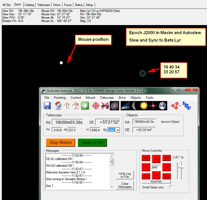
Posted By: georgecarey47 Fri May 3, 2013 1:54 pm
I have never been able to get Autoslew, Maxim and Cartes du Ciel to give
consistent coordinates for objects and where the scope is pointing.
If I set all three to J2000 there is a big offset. This image shows Maxim when I
have slewed and synced on Beta Lyr.
http://geoastro.co.uk/may2013/coords.jpg
Autoslew says 18 50 3.38 and +33 21 52
The star coordinates are 18 50 05 and +33 21 46
To get the mouse position coordinates the same as Autoslew I have to move
slightly away from the star.
The circle that indicates where the scope is pointing is way off to the side.
If I set Autoslew to 'Real' and Maxim to J2000 the agreement is closer but not
spot on.
Can someone please give a guide on how to get everything in agreement?
George
_____________________________________
Posted By: jbaj82 Fri May 3, 2013 2:04 pm
I have the same issue. Most of the time I send slew commands to Autoslew over
Ascom in J2000, while Autoslew indicates "real". That way I get the best
pointing results.
_____________________________________
Posted By: nischangde Fri May 3, 2013 3:18 pm
Hi George,
the same problem happened to me, running Autoslew, Maximdl and Guide 8. Doing
all slews (except "Dither via mount") from Guide, I found out the most accurate
setting is to use "Real", called "Mean of Date" or (Mean) in Guide.
cs
Martin
_____________________________________
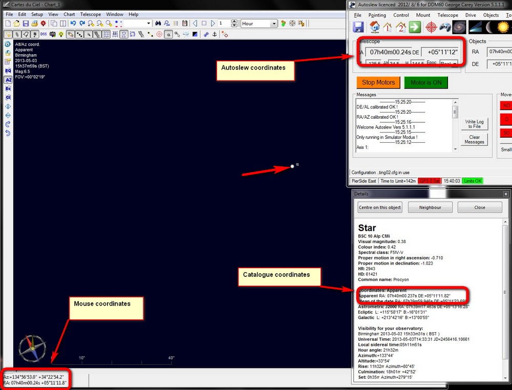
Posted By: georgecarey47 Fri May 3, 2013 4:54 pm
I think I may have cracked it.
Step 1 Upgrade to a newer version of Cartes du Ciel
Step 2 Set Autoslew to 'Real'
Step 3 Set Cartes du Ciel to 'Apparent, (true equator, equinox and epoch of the
date)
I now get everything displaying the same coordinates - see here
http://geoastro.co.uk/may2013/screen.jpg
Now I have to see if I can get asteroid and comet coordinates in the same form!
George
_____________________________________
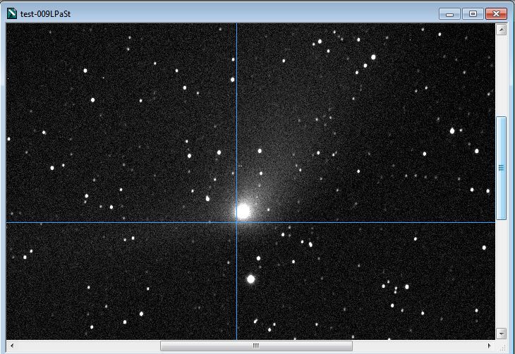
Posted By: georgecarey47 Sun May 5, 2013 1:09 am
I had the chance to try a few tests tonight. With Cartes du Ciel and Autoslew
both set to 'Real' coordinates pointing was excellent. I have amended my
spreadsheet for making object lists so that it will now extract J2000
coordinates from the ephemeris.
The coordinates in the pointing list are set to J2000.
When Autoslew runs through the object list it converts the J2000 coordinates to
Real. This image was the first slew to comet Panstarrs at 10:30pm (BST). The
slew started at the other side of the sky in Hercules.
http://geoastro.co.uk/may2013/test.jpg
That is close enough for me!
The object list looks like this:
8
*****************************
Object Number 1
Object Name :21:00 C/2011 L4
Epoch: 2000
RA : 0.0824444444444444
DE : 70.4908333333333
*****************************
Object Number 2
Object Name :21:30 C/2011 L4
Epoch: 2000
RA : 0.0817777777777778
DE : 70.5083333333333
*****************************
Object Number 3
Object Name :22:00 C/2011 L4
Epoch: 2000
RA : 0.0811388888888889
DE : 70.5255555555556
*****************************
Object Number 4
Object Name :22:30 C/2011 L4
Epoch: 2000
RA : 0.0804722222222222
DE : 70.5430555555556
*****************************
Object Number 5
Object Name :23:00 C/2011 L4
Epoch: 2000
RA : 0.0798333333333333
DE : 70.5605555555556
*****************************
Object Number 6
Object Name :23:30 C/2011 L4
Epoch: 2000
RA : 0.0791666666666667
DE : 70.5777777777778
*****************************
Object Number 7
Object Name :00:00 C/2011 L4
Epoch: 2000
RA : 0.0785
DE : 70.5952777777778
*****************************
Object Number 8
Object Name :00:30 C/2011 L4
Epoch: 2000
RA : 0.0778333333333333
DE : 70.6127777777778
I have set the object 'name' as the time and the comet identification which
shows up neatly in the Autoslew window.
George -
This is a transfered topic from the ASA Yahoo Group.
Posted By: pauloastro69 Fri May 3, 2013 5:36 am
Hello everyone,
I have set in AS the option "how far can you go through the Meridian with your
German Mount?" to '-12' degrees, and the telescope is not hitting the west side
of the pier with the counterweight pointing est and a meridian flip is
happening.
But the problem now is that after the meridian flip and the counterweight
pointing west the mount try's to approach the object from the est side with the
telescope hitting the est side of the pier.
Is it possible to avoid this?
Is there a way to set a limit on the est side too?
best regards,
Paulo Nunes.
_______________________________
Posted By: jbaj82 Fri May 3, 2013 10:00 am
Why did you fill in a negative number, can't you go through the meridian with
your setup?
What value do you use with "Minimum flip distance for east-side slews"?
Regards,
Jeffrey
_______________________________
Posted By: pauloastro69 Wed May 8, 2013 2:41 pm
Dear Jeffrey,
Yes, I use a negative value for "how far can you go through the Meridian with
your German Mount?" option, because my newton telescope will strike the pier.
For the "Minimum flip distance for east-side slews" I'm using the same value of
-12 degrees or the same as the "how far can you go through the Meridian (...)"
option.
Best regards,
Paulo.
_______________________________
Posted By: bernd_eppinger Wed May 8, 2013 10:32 pm
Hi, Paulo,
To be honest, I don't think I understand what you are trying to achieve.
You say you must enter a negative number (-12°) for "How far can you go through the meridian...", because otherwise your telescope hits the pier when the counterweight is on the east side. My conclusion is that your telescope can't reach the meridian when coming from the east side before hitting the pier. However, if your pier (or probably tripod) is symmetric, you have the same problem on the west side, i.e. when approaching from the west side, you can't come closer to the meridian than 12° either.
In this situation, you want to make a meridian flip. But you have no position in the sky which you can reach from both sides of the pier. Moreover, there's a remarkable gap of 24° with celestial positions which you can't reach at all (simplification, not taking into account that in reality the distance to the meridian depends on the altitude, too). Now when your observed object approaches the meridian from east and comes closer than 12°, you can't make the required meridian flip simply because you can't reach this position from any side of the pier.
Assuming I understood your problem correctly, my proposal would be to solve the underlying mechanical problem. For example, if you have a tripod, you can create more room for your telescope by adding a pier extension (which is what I did). I admit that it is difficult to precisely calculate the required length of the pier extension in advance.
Best regards,
Bernd
_______________________________
Posted By: pauloastro69 Fri May 10, 2013 11:35 am
Hello Bernd,
Thank you for your reply.
">there's a remarkable gap of 24° with celestial positions
which you can't reach at all".
Yes, your explanation of my problem is correct..
My pier, not tripod, is a 30cm square made of concrete, and 50cm height from the
ground.
I was trying to automate my observatory after manually opening the roof but with
my present telescope, the AG14, and my actual pier there is always this 'small'
problem. With my last scope, a C11, the pier configuration was perfect. But now
with the AG14 I really have to make serious mechanical changes in one or both.
I was hopping to delay this problem some more time with a software configuration
change, but as this seems impossible with Autoslew I will have to address this
sooner.
Thanks again, Bernd.
My Best regards,
Paulo.
USB problems
in Software
Posted
This is a transfered topic from the ASA Yahoo Group.
Posted By: mattssporre Wed Feb 1, 2012 4:47 pm
Dear all,
I have recently gotten a lot of USB problems.
The mounts USB hub acts like a USB1.1 hub. The camera attached to the mounts USB
hubs supports USB2.0 and image downloads that used to take max 5s now takes more
than 30s.
I know the mount use the FTDI driver (serial to usb driver). So what I did
before (the problem is not new) was to
1. uninstall the mounts com port
2. disconect the mount (USB)
3. uninstall the FTDI driver (CDM20814-setup.exe)
4. Restart
5. Install the FTDI driver
6. Restart
7. Connect the mount (USB)
8. The drivers re-installs
One thing that complicated things was that I also have the OK3 focuser and the
flatman also running on the FTDI driver (so in the above I needed to uninstall
and unplug also those).
Now the above does not work anymore. The mount USB hub stays at USB1.1.
It is def the mounts USB hub, since if I take the camera and plug it directly to
the USB port in the PC (that the mount is connected to), USB2.0 works fine.
Does anyone recognize this problem? Solution?
BR
Matts
PS at present I am having more problems with the DDM60 and the N10 than there
are drops in a rain...
________________________________________________________________
Posted By: erwin_kats Wed Feb 1, 2012 5:35 pm
Matts,
I was having the same problem, and mostly even connection lost to the ccd with the internal usb hub in the ddm 85.
After a upgrade of the mount i do not have this problem anymore.
I also think the usb to serial is only for the mounts control and not for the usb hub ( this is the experience i have )
Kind regards, Erwin Kats
________________________________________________________________
Posted By: mattssporre Wed Feb 1, 2012 8:21 pm
Thanks for the info Erwin. With upgrade do you mean the firmware uppgrade?
BR
Matts
________________________________________________________________
Posted By: erwin_kats Wed Feb 1, 2012 8:27 pm
Matts,
Sorry for my not full complete information.
My mount has been upgraded from before may 2010 to after may 2010 model.
at that moment there was also placed a powered USB hub in the mount on my request because the other model had a non powered usb hub.
Kind regards, Erwin Kats.
________________________________________________________________
Posted By: philipp_keller Wed Feb 1, 2012 8:42 pm
the hub is only a hub, it can't have anything to do with the mount or its
drivers.
________________________________________________________________
Posted By: mattssporre Wed Feb 1, 2012 8:53 pm
Ok,
So then I do not understand why the USB2.0 does not work anymore when I connect the camera via the mount. It works if I connect it directly to the PC (using the same usb port that the mount is connected to)?
Also, before I could make it work if I uninstalled the FTDI driver and installed it again.
The mount (usb to serial) and the internal usb hub shares the same usb port on the PC.
BR
Matts
________________________________________________________________
Posted By: bernd_eppinger Thu Feb 2, 2012 12:38 am
Hi, Matts,
As far as I know, the FTDI-chips are endpoints in a USB system, like USB-sticks, GPS, cameras, mouse etc. At least I am not aware of USB hubs made by FTDI, which means the hub is likely a separate chip in the mount. So I guess what Philipp wants to say is that the FTDI drivers should have no effect on the hub.
I find it strange that the hub first worked in USB2.0 mode, and now only works in 1.1. It is still the same hardware. I wonder if this is one of the typical WINDOWS problems with USB. At least for WINDOWS XP, I was able to solve a problem with an USB stick by the following procedure which I had found somewhere in a Microsoft Knowledge Base article:
I don't know if that helps, I only know that it helps me sometimes with USB problems.
Best regards,
Bernd
________________________________________________________________
Posted By: mattssporre Thu Feb 2, 2012 1:00 am
Hi Bernd
thanks a lot - those sounds like useful tips. I will try them out tomorrow.
There is one I do not know how to do
In System Control, add the following environment variable:
devmgr_show_nonpresent_devices=1
Where do I find System Control?
BR
Matts
________________________________________________________________
Posted By: mattssporre Thu Feb 2, 2012 12:25 pm
Hi again Bernd
I found it out - the english word is Command Window and the line to write is
set devmgr_show_nonpresent_devices=1
I had a lot of hidden devices under USB (in gray). I removed them all, started
the mount etc and the different things (filter wheel, CCD camera, ASA
Elektronik, ...) re installed itself, but unfortunately the problem still
remains.
Thanks anyway.
BR
Matts
________________________________________________________________
Posted By: tomtom2509 Thu Feb 2, 2012 3:51 pm
Hi Matts,
I sometimes have also the same problem. It happend when I mixing USB 1.1.
devices with USB 2.0 devices. For exaple if I connecting my usb 1.1 filterwheel
first at the hub, it "downgrade" the hub to 1.1 and after connecting the camera
second, the hub still works in 1.1.-mode. So in such a case, I have to make sure
to connect the camera first an afterthat the filterwheel.
Very frustrating if you want go in a remote setup.
Even the circumstances, that it just happend sometimes, makes it more confusing.
BR Thomas
________________________________________________________________
Posted By: mattssporre Fri Feb 3, 2012 12:00 am
Hi Thomas,
Thanks, I will try that.
BR
Matts
________________________________________________________________
Posted By: philipp_keller Thu Feb 2, 2012 8:46 am
the hub does not need any drivers. It has some simple IC inside and simply
splits the USB cable in severak ports.
The FTDI driver is needed for the USB connection of the mount.
I suspect its some strange Windows problem but I would say the mount is not
guilty here.
Maybe the USB workload is to large and he slows down the camera ?
Did you try to turn on the mount but do not start Autoslew and then connect the
camera ? Does it show as USB 1 or 2 ?
Best,
Philipp
________________________________________________________________
Posted By: mattssporre Thu Feb 2, 2012 11:09 am
Hi Philipp
In 90% of the cases when I have had this problem Autoslew was not started, the
mount was powered (the camera uses the internal power of the mount).
The reason is that the last thing I do is to start AS, so I see this problem
(there is a notification in XP something like "this unit could work faster if
connected to a USB2.0...") before AS is started. I have also seen it in
situations when I am about to take darks (AS not necessary).
In addition it has worked before. A year ago there was no problems, then they
slowly started to appear and now I can not make it go away.
The first few times it happened I thought there was some error on the PC USB
port so I changed USB port on the PC (the cable from the mounts usb port to the
PCs usb port). The "ASA astroptik" installed itself and then it worked again,
but only for a few days, and I ran out of USB ports on the PC. Connecting the
mount to a PC usb port that the mount had previously been connected to just
resulted in the error right away. This was when I tried to connect the camera
directly to the PC and that always worked fine and my conclusion is that for
some reason, the internal USB hub gets downgraded to USB1.1, since the PC port
definitely is USB2.0.
I agree and would not be surprised if this was a Windows XP problem, so I will
check out some of Brends tip. As a backup plan I have my laptop that I am about
to reboot to a fresh installation (Vista is on now...).
BR
Matts
________________________________________________________________
Posted By: philipp_keller Thu Feb 2, 2012 7:07 pm
Hi Matts,
did you try to uninstall the FTDI Driver in the device manager when having the
telescope connected by right click on this device and select uninstall.
Also on the FTDI website there are some tools to completely remove the FTDI
driver.
I remember one case where I could not connect to the mount any more and it took
some time for me until I really removed the destroyed FTDI driver.
I still don't understand why the FTDI can have anything to do with the HUB but
its not always logic that helps you with Windows.
Also try with another PC.
________________________________________________________________
Posted By: mattssporre Thu Feb 2, 2012 11:59 pm
Hi Philipp,
thanks for the input.
What I normally do is to
1. open the device manager
2. open com/LPT port list
3. uninstall the com port the mount is connected to (right click and chose
uninstall)
4. Unplugg the mount
5. Run the CDMuninstallerGUI.exe (which is the tool you write about) to
completely uninstall the FTDI driver
6. Restart the PC
7. Run CDM20814_setup.exe to install the FTDI driver again
8. Restart the PC
9. Connect the mount (and watch how the different components reinstall
themselves, ASA Elektronik, USB, etc).
What I realize from Bernds post is that every time I did this I created a new
USB connection in the device manager (that is why I had so many hidden).
Probably because each new FTDI driver installment logically created a new USB
port and therefore the ASA Elektronik, etc re-installed itself on that new port.
In addition the OK3 focuser and the flatman also uses the FTDI driver, so when I
had removed the FTDI completely I also had to unplug the OK3 focuser and the
flatman.
I am left with
a. Check the power consumption (from Wolfgangs post). There are a number of ways I can do this.
b. Try using my laptop (just need to reboot it).
c. Try uninstalling the FTDI drivers (as per above) and also uninstall the
camera and filter wheel. Being careful to plug in the camera first (as per Tomas
post).
BR
Matts
________________________________________________________________
Posted By: ic2779 Thu Feb 2, 2012 11:19 am
Hello Matts
I´m pretty sure it is a camera power problem, I had that with a insufficient powersupply.
The camera the reverts from USB 2 to USB 1 for instance when you turn the cooler on.
________________________________________________________________
Posted By: mattssporre Thu Feb 2, 2012 12:25 pm
Thanks for the reply Wolfgang
It could be, but it does not explain why I could (before) make it to work again
after removing and reinstalling the FTDI drivers.
Similarly in the beginning, when the problem started to arise I could solve it
by changing USB port on the PC.
Also it works, using the same power supply if I connect the camera directly to
the PC (then again, I never tried this with the mount fully powered).
I guess I can check this by measuring the Amps and Volt of the camera when
everything is up and running.
BR
Matts
________________________________________________________________
Posted By: dale.liebenberg Thu Mar 29, 2012 8:30 am
Hi All,
Because of previous problems, I invested in an active USB exention cable to an
active USB hub on the mount. The DDM60 and 2 cameras and filter wheel are
connected to this USB hub.
Last night the mount failed with this message:
-------------04:46:56------------
Axis RA/AZ reported the following Problem:
WriteInt16 Error USB Nr. 5, 2 tries
-------------04:46:54------------
Axis DE/AL reported the following Problem:
WriteInt16 Error USB Nr. 5, 2 tries
etc
However, there were no failures on any of the other USB devices.
My USB connection on my mount is the flat connection and not a printer type. As
this is not a very solid connection, I suspect this connection.
Has anyone had a similar problem? A possible solution?
Dale
________________________________________________________________
Posted By: lukasdemetz Mon Mar 25, 2013 6:51 pm
Hi there,
after a long time (since november) where I have been working on my new observatory, I mounted today my upgraded DDM85XL.
Everything went smoothly, I also connected all cables and checked the connection with Autoslew – perfect.
After a few trials of slewing around I noticed that, when slewing at “higher” speeds (above 1-2°/sec) I seem to loose the USB connection after a few seconds. Autoslew then attemps to restore the USB connection (software unplug and replug, as they call it). The funny thing is, Windows doesn’t notice that the connection got lost (in fact it continues to display the device under the Devices).
Now, tomorrow I will go and do some troubleshooting on-site, but just in case if someone has an idea where I should look, you’re welcome J
My first thoughts were:
Thanks (and I’ll keep you informed)
Lukas Demetz
________________________________________________________________
Posted By: lukasdemetz Tue Mar 26, 2013 10:42 am
Alright, figured out that the active USB cable was the problem. I changed it with a “normal” 5 meter USB cable, and voila, it works.
I still get connection losses when the current the mount needs goes too high.
________________________________________________________________
Posted By: jbaj82 Tue Mar 26, 2013 1:34 pm
Hi Lukas,
How do you know that the USB has lost connection?
Regards,
Jeffrey
________________________________________________________________
Posted By: lukasdemetz Tue Mar 26, 2013 1:38 pm
Hi Jeff,
well, Autoslew tells me that it lost the connection and is attemping to restore it, by a “software unplug event”. After this, it sometimes is able to regain the connection, and sometimes I have to shut down Autoslew, power cycle the mount and then it works again.
But beware, I still have to test this under the real sky.
Best regards
Lukas
________________________________________________________________
Posted By: bernd_eppinger Wed Mar 27, 2013 9:40 am
Hi, Lukas,
Do you have the possibility to find out if the power-supply goes into current limit for a short moment when you have a connection loss? Perhaps your power-supply might have an LED that signals the current limit? Measuring it with a digital voltmeter might be too slow, and I assume that you don't have an oscilloscope.
Another possibility might be a long (and/or high impedance) cable between the power-supply and the mount. This could not only cause voltage drops at the mount in case of high current consumption. In addition, if both your computer and the power-supply output are grounded to the Earth-connector of the wall-outlet, then it could cause a voltage-drop along the ground-connector of the USB-cable (and a high current) which is proportional to the current consumption of the mount. This voltage drop could interfere with the USB connection. The effect is called "ground loop".
High impedance connectors due to e.g. corrosion might have a similar effect as a high impedance cable, but as your equipment is new, I don't expect this to be your problem.
By the way, the ground-loop effect would be worse if your USB-cable is long and has a high impedance of the ground connector. Thick USB3-cables that are rated for high currents may be less sensitive to the effect, but if you have a ground loop, then the USB-cable is not the root cause but the symptom.
Best regards,
Bernd
________________________________________________________________
Posted By: bernd_eppinger Thu Mar 28, 2013 9:02 am
Hello, Lukas,
OK, that should be good enough. I, too, use this cable, and it works. Although I must say that I have a DDM60 which I have never seen drawing the specified 10A. And my power-supply has a floating output, i.e. its output is not connected to Earth.
The ground loop effect would be strongest if you had a high impedance power supply cable to the mount, which seems not to be the case. There are other parts which could contribute to a ground loop, but for those, I could not easily explain why the effect should depend on the Mount's power consumption. So I would not see this as a likely reason anymore.
Anyway, to minimize those other effects, the mains cables from the wall-outlet to the mount power supply and to the computer power supply should be as short as possible. Besides, they should be connected to the same wall-outlet or to the same extension lead. As a last resort, it might help to find a low impedance ground at the computer (usually the chassis) and at the mount (I am not familiar with the DDM85) and connect them by a thick cable.
A ground loop only happens if both the mount power supply and the computer are connected to Earth. For the computer, this is usually the case. For the mount power supply, you can check it with an ohmmeter by disconnecting everything from the power and measuring the resistance between the negative output and the Earth connector of the power cord.
I would not recommend to disconnect or interrupt the ground connector of the mains supply cord, because in this case, you are no more protected against certain types of power supply failures. This can put your health at risk. I admit that privately, I disconnect it sometimes for a short time if I see no other way to make a sensitive measurement. In my company, I am not allowed to do this. There I have built a special circuit which has a similar effect for small signal, but still protects me reliably against failures, and I got a VGB approval for it.
Best regards,
Bernd